
Welcome to Rocky Plains Observatory (your feedback on my site is always welcome, particularly if something is not working right).
Like most amateur astronomy buffs, I've dreamed of an easier way to make observing a more convenient activity. Hauling my equipment up out of the basement (and tiredly back down late nights) has gotten to the point where I too often skip the opportunity and miss out on far too many clear nights (and days).
The obvious answer was to build a backyard observatory. It's something I've dreamed of for years, but have always put off. Now that I have finally completed and begun using mine, I can finally understand what so many friends have told me. The only regret is that I didn't do this sooner...
The hardest part is just getting started. Thanks to the internet, I have drawn plenty of inspiration and numerous ideas that got me going. I hope my site can do the same for you. Click the link below and have a look.
The Observatory
Here you'll find links to information on the planning and construction details of my observatory, as well as the equipment I am using. I've tried to include plenty of detail and descriptive information, but hopefully the pictures will tell enough of the tale, and help you with your own observatory project. Most of the pics are in the Construction section, and are 70kB or less in size.
Planning
What kind of roof?
The first question that came to mind when I planned out my observatory was what kind of roof? It's only logical to answer this question before proceeding with plans, as the roof type pretty much dictates many of the design decisions. One of my primary goals was to match the architecture of my home, at least to a reasonable degree. Keeping my wife and neighbors happy was a prime concern.
A dome would have probably 'stuck out' too much for my location, though who can resist the appeal of a dome - that screams astronomy? Domes offer some obvious advantages, notably shelter from wind and more comfort in winter. A dome would also give great insulation from stray light and provide a very dark environment. Of course, there are downsides. Cost is the biggest, as I was unwilling to tackle the design and construction myself. Decent commercially available domes were far too expensive. I wondered about thermal effects (slower cooldown, air currents through the aperture). Also, in the inevitable event that I need to sell my house, a dome could be a detractor (unless I make it easily convertible back to a standard roof, for use as a shed).
Architecturally, a roll-off would blend in and look less obvious (also a security concern). Architectural concerns aside, a roll-off design would be much cheaper and I could do all the work myself. A roll-off has a lot going for it. Being able to quickly open the entire building to the night sky provides rapid cooling. It also comes closest to being out in the open under the stars, and the walls provide enough shelter from surrounding light and houses that I can still feel less like I am in an urban backyard. The mechanical simplicity of a roll-off is a real plus. Movement on rollers is such a simple approach, and standard roof construction is easy to pull off with materials that are easy to find.
I spent some time considering less standard designs. Most revolved around different ways to hinge open or clamshell the roof(s). The challenges of supporting, counterweighting, and dealing with snow loads added complexity and structural challenges, without any significant benefits. Some commercial segmented clamshells appear to offer a neat compromise, being able to fully or partially open, but again cost becomes a factor, as does architectural look.
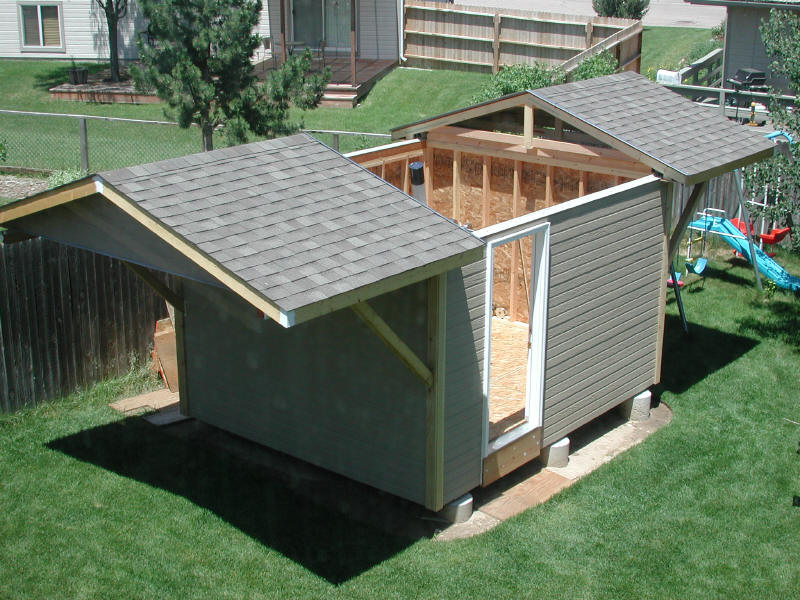
In the end, a roll-off became my obvious choice and early on I settled on this approach. Rather than a one piece roll off roof, however, I opted to split the roof in two. One half of the roof rolls to the south, and the other half to the north. This has some real benefits. Having to roll only half a roof reduces the mass that I need to roll at one time. A split roof also allows you to close the roofs down except for the region you are viewing, which is nice on very windy cold nights (almost like a variable width slit). Architecturally, the 'outriggers' that the roofs roll out on extend from both sides of the building - but are only half the length of a single roof, and can be cantilevered from the building without requiring vertical support columns.
Size
One thing I learned (and was constantly reminded of by others) was to make the building as large as possible. Practically, however, I did have some limits. Given the space I had available, and some local building codes, I settled on a 10'x12' size. I had been in some other small observatories, and found that 10x10 was about the minimum I could tolerate, and 10x12 offered just enough more space to be able to locate a computer at one corner and still have room for some shelves and seating area for visitors. I planned to use some pretty long scopes as well, so 10 x 10 would have probably been too small. One other consideration was the local building codes. At 120 square feet and smaller, no building permit was required for a structure of this type and purpose. Though I could certainly have gone larger and gotten a permit (and the necessary plans and inspections), being able to skip that hassle was a plus. In hindsight, I wish I had gone a little larger (12X14), but 10 x 12 worked out nicely and isn't too imposing in my yard.
Building Height
One of the tradeoffs that I had to make was how high to make the walls and how pitched to make the roofs. I wanted the walls to be tall enough to obstruct some of the surrounding environment without blocking too much horizon. Also, the taller I make the walls, the higher the roof peaks would be. I wanted to maintain a decent southern horizon, especially for low objects like Mars this past apparition (it was very low this year). I settled on a wall height of 76 inches (to the rail mount surface), which has worked out pretty much as I had wanted. When seated at my scope, I am very isolated from all but the night sky above, and the wind is directed just above my scope. One consideration that I learned of was the impact of wall height on door size. Given my wall construction (4x4 top beams for the roof rails), a standard door had to be cut down about 5 inches. Since I wanted a steel (foam core) exterior door, I had to cut the door down (a real pain). Commercial custom steel doors are very expensive, so I had to do this myself (a weekend's worth of work). If I had it to do over again, I might consider making the walls just enough higher to not need a custom door.
The roof pitch was another question. I settled on a 4/12 pitch, as it was about the minimum that drained well, using composite shingles, and it had enough pitch to blend with my house. Any steeper and I would lose too much southern horizon. As it was, I ended up extending the south rails so I can roll the south roof off 2 feet past the edge of the building
Location
I had originally dreamed of building an observatory on land in the mountains, or out on the surrounding plains away from city lights. However, as I talked to friends with observatories and gave this some serious thought, I realized that to be truly useful for me, I needed a building as close as possible - in my backyard. What a joy it is to be able to so quickly enter the building, put on some background music, roll off the roofs, switch on the mount, and head into space. City lights are certainly a problem here (on the best nights, the summer milky way is faintly visible when overhead). However, there is plenty I can do from my backyard. Planetary and Lunar viewing is a primary interest, and having an instrument close to thermal equilibrium that I can use at a moments notice is a real key to being able to catch nights of decent seeing. Though deep sky views are not too impressive, the brighter nebula, star clusters and double stars still offer plenty to view. Of course, CCD imaging still works surprisingly well in moderate light pollution. So, in the end, a backyard location was my choice, and after a couple months of usage I know I made a good choice.
I had already decided where in my yard the building would work best, by being farthest from surrounding trees. A small bed of shrubs had to be taken out (some of the bushes had some serious roots!).

Design
Floor/Foundation and Pier
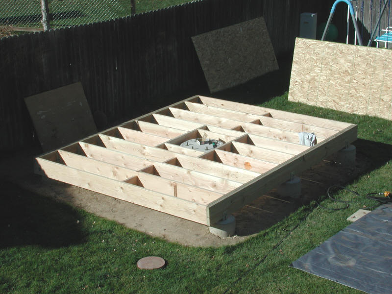
One of my primary goals was to make a minimal thermal-mass structure to minimize impacts on local seeing from lengthy building cooldown (in Colorado, night to day temps are widely varying and there is significant falling temps through the entire night). This led me to select a raised wooden floor over a solid concrete slab. This also was a lower cost solution, and one that was easier to build myself. The floor is isolated from the central pier to prevent unwanted vibrations transferring to the telescope. I made the floor beams oversized (2x10 outer beams, 2x8 floor joists), mainly to impart a very rigid feel so that it doesn't feel like a raised floor.
The central pier for the telescope consists of the base concrete footer, and a bolt on steel pier. The concrete footer is 4 feet deep, and is 3 feet in diameter at ground level, expanding out to 4 feet in diameter at the bottom. The concrete also extends about 18 inches above ground level - I formed this portion using a 24 inch diameter concrete form tube. The concrete is fully reinforced with a rebar cage that extends the full length. Six 3/4 inch J-Bolts were set into the concrete using a plywood disk as a jig. The steel fabricated telescope pier fastens to the concrete using these six bolts. The plywood jig also resulted in a flat concrete surface so that no shimming or grout was needed to seat the steel pier.
The steel pier is made from a 52 inch long piece of 12" ID x 3/8" wall steel pipe (bought at a local salvage yard), to which a 3/4" thick 20" diameter bottom flange has been welded. This flange bolts to the concrete pier through six radial slots (to permit some rotation adjustment for polar alignment). The top surface of the pier was also made of 3/4" steel plate, and was pre-drilled and tapped for several common large telescope mounts (1200GTO and Paramount ME). The basic design goal of the pier was to provide high rigidity, and still provide a clean appearance and freedom from tripping when using the scope. Many commercial and amateur pier designs use smaller diameter pipe, and try to gain back some stiffness through base gussets. These gussets add fabrication expense, and do not provide near the stiffness of simply using a larger diameter pipe (wall thickness is a secondary factor - diameter is the primary consideration in stiffness).
The pier height was chosen to provide a good compromise between being tall enough to allow me to be seated when using a long refractor at zenith as well as when observing 20 degrees above the east or west horizon. I found that this condition occured when the intersection of the declination and RA axis fell approximately at my eye height when standing.
For some pics of the pier, go to the Equipment section.
Roof Design
I spent quite a bit of time working out the roof and wheel/track design. I began by designing the wheel and track details, as the rest of the roof design really flowed from there. I surfed through all the ideas and designs that others have posted on their sites, and found a wide variety of unique and clever designs. However, none of them directly suited my goals. I wanted a very easy to roll system that added minimal vertical overhead (I wanted to keep the roofs as low as possible to maintain my southern access). I also wanted the roof to be captured from lifting off (wind) no matter whether open, closed, or anywhere in-between. The exposed tracks needed to shed rain and snow. The wheels, tracks, and truss design also needed to be designed to support the potential snow loads in this region, which can reach 30 lbs/sqft (roof projected area).
The best solution that I found was to use commercially available V-Groove wheels running on inverted angle iron. This design provides low friction while still controlling lateral (side to side) movement. Standard wheel/track designs that use wheels rolling in straight sided channels tend to have higher friction forces from the side rubbing of the wheel to track interface. The large 6" diameter wheels enable very low friction to roll the roof, and their bearings were more than able to support the maximum roof weight, though I do not plan on rolling the roof off fully loaded with snow.
Another primary goal of the roof design was to blend in and look as much like a standard (non-rolling) roof as possible . The only obvious clue that the roofs roll off are the two cantilevered track beams. The soffits return up under the tracks, forming a full length capture that prevents the roof from lifting off in any position. The soffits also impart a standard look to the roofs.
For some images that illustrate the roof design details, go to Roof Construction.
Thermal Considerations
As mentioned above, one of my goals was to make the structure as thermally light as possible. The walls are standard frame construction, and when completed will be insulated with fiberglass batting. The roofs are also insulated with 4 inches of closed cell foam (R20). Framing for an exterior opening is already in place, and will be used to mount a small window air conditioning unit. Rather than try to aggressively ventilate the building (to keep peak summer temps down), I opted to thoroughly insulate the building. Even without air conditioning, this will keep the peak temp below the outside temp - but will slow late afternoon and early evening cooling (with roofs closed). In order to be able to rapidly use the telescope (at equilibrium), I will use the small air conditioner to keep the typical temperature under 80, then pre-cool closer to the evening temps. One concern I have with such a minimally ventilated structure is condensation. So far, I have not experienced any problems (most likely due to my generally arid environment). I am now adding some raingutters to further channel water away from the building. A benefit to having a more sealed structure is the minimization of windblown dust (and bugs!) getting into the building and onto my equipment.
Misc Details
Though not completed (saved for next Spring), I will be finishing the interior using the darkest wood paneling I can find (or stain my own). In my urban location, I want to create as dark an environment as possible to assist in dark adaptation. I cannot do anything about sky brightness, but by darkening the walls (and using dark gray carpet), I can significantly darken 50% of the area around me.
Construction
Construction took me approximately one year from when I broke ground until the scope was in place and operational. I did almost all of the work on my own, but had some invaluable help for some of the tasks (concrete, roof installation, siding). I was able to get all the groundwork in place prior to the winter (before the ground froze). Over the winter, I completed some of the remaining design details, and pre-fabricated all of the roof components. This included the machining and welding of the wheel beams and tracks, as well as building up the roof trusses. I was able to do all this indoors, so when warmer spring temps arrived I was ready to go. As it turns out, this was a great strategy - the building went up very quickly as a result, and the precision work was already done.
Foundation
Groundwork
The first order of business was to accurately layout the locations of the holes for the six footers (for the floor) and the central hole for the telescope pier. Batterboards were staked and mason's lines layed out to mark hole centers. Then the fun started...
The floor footers required 12 inch diameter by 3 foot deep holes, needed to get well below frostline. I rented a 12" tow-able auger that worked out great, but I constantly hit 2-6 inch rocks that required me to remove the auger and break the rocks out by hand (one of the origins of the Rocky Plains in the name of the observatory). I also used the auger to pilot the telescope pier hole by drilling 4 holes which I broke up and dug deeper by hand (the auger only drilled 3 feet deep and I wanted the central pier to be 4 feet deep). The holes were all belled out by shovel, so that they had a wide footing to spread the load and further prevent the piers from heaving out by frost.


Concrete Forms
The concrete footings and pier were fully reinforced and sonotube used for the above-ground concrete forms. The small forms were driven tightly about 12 inches into the holes (and then backfilled after pouring), but the central pier was a bit more complex. A 2 foot diameter form tube was used for the 18" above ground protrusion. This tube was fastened to a 4'x4' plywood collar, which capped the 3 foot diameter hole. When the central pier hole was filled to ground level, the form cap was added and the remainder poured. A plywood plate had been pre-assembled with the (6) 3/4" J-bolts (for bolting down the steel pier). This plate was also very flat and resulted in a smooth, flat top surface (I carefully leveled the plate as well). The central pier was reinforced with a cage of rebar rods and hoops (formed hoops are available cheap from local concrete supply houses). Batterboards were left in place until after concrete was poured to enable precisely locating post anchors to be pushed into the wet concrete.


Concrete Pouring
Rather than mix 2 yards of concrete by hand, I chose to pay a little extra to have the concrete delivered (the difference in cost was less than $100 once you figure the cost of renting a small mixer). The tradeoff is that you need to be able to pour quickly, as the concrete company charged extra after 1 hour of site time. I tried to get everything completely ready to pour, lining the path with plywood and making a ramp and wheel stop at the edge of the pier hole for dumping. I assembled a crew of coworkers, bribed with the prospect of cold beer after completing the job... We had 4 wheelbarrows that were used to ferry concrete from the street back to my backyard (don't want the concrete truck driving onto my driveway, as they are not designed to carry that kind of load). I was a little nervous, but as it turned out the whole job went very smooth and fast (it only took about 30 minutes).


Framing
Floor Construction
The floor design called for a straightforward arrangement of doubled up 2x10s to form very solid beams along the 12' east and west floor perimeter, with 2x8 joists spanning the 10' in between. The beams were leveled and nailed into the (6) post mounts that had been set into the concrete footers. The 2x8 floor joists were fastened to the beams using sheet metal joist hangers. I took great care to get the framing square.
After framing, the floor was sheathed using 3/4" tongue and groove waferboard. Sheathing was glued and nailed using ring nails. I also attached 1" foil backed insulation on the undersides of the sheathing prior to installation. This was to act as a moisture barrier and provide a little insulation. If needed, I will cut vents in the ends of the beams later for air flow (haven't done that yet).
An important feature in any observatory is cable management. Being able to easily add or remove cabling is a key point, and I wanted flexibility to change routing in the future. I designed the floor so that cables can be routed underneath two removable panels that simply set into place. Secondary panels are permanently screwed below these panels to seal the cable routing spaces. In this way, I can easily route cabling to the east or west of the telescope, or cross completely under the floor from one side to the other. Above the concrete pier is another panel that will have a 13" hole cut in it for the steel telescope pier to protrude through. The concrete pier and 3/4" bolts are located just below floor level. Another panel seals the space around the concrete pier, with a 1/2" gap all around sealed by foam rubber (floor remains isolated from the concrete pier to prevent vibrations reaching the scope).
I completed the floor in October, and kept it covered by a tarp all winter, while working on the roof components.


Wall Framing
After a winter of completing the roof pieces (see Roof Fabrication) and working out all the remaining final design details, spring finally rolled around and warmer weather allowed me to complete the framing. Weather in Colorado is extremely variable, so when I saw a span of several promising days, I jumped in and got going (one day in May while I was putting down the roofing felt we went from a calm day of 80 degrees to the high 30s, light snow, and 70MPH wind gusts - all in the span of under 2 hours!).
The wall framing was very straightforward, using 2x4s on 16" centers. I built and sheathed the walls one at a time flat on the floor, then tilted them into place. Having a square floor really paid off here, as everything came out extremely plumb and square. Sheathing (3/8" OSB exterior grade) was glued and ring nailed (a nail gun came in real handy here). Honey, I just Have to Have that new nail gun... Be sure to leave small (1/16") gaps between sheathing seams, to account for expansion/contraction. When done, I wrapped the building with a moisture barrier (similar to Tyvek). I told my neighbor I was fond of pink and was going to leave it that way...


Roof Construction
Wheel Beam Fabrication
The heart of the roof design are the wheel beam assemblies. These beams are made up of 3x3 steel tube (1/8" wall), and were machined to house 2 wheels each. The 6" roller bearing wheels are commercially available, and have a central machined V-groove wheel that is designed to ride on inverted angle iron. A 3/4" hardened steel shoulder bolt serves as a wheel axle. The end wheels are mounted inboard from the end of the beam to enable the roof to overhang the cantilevered track beams, to minimize the length needed for the roof to completely roll off the building.
Four angle cross pieces are welded to the top of each beam, to provide attachment to the roof trusses. The trusses are bolted to these angles through slotted holes, to enable fine tuning (adjustment) when building the roof in place on the rails.
Though I had learned to weld in college (too many years ago), I was able to pick it up well enough to get the job done - but my welds weren't too pretty. The structural requirements for all these welds are very minimal. I used a simple AC-DC arc welder (Lincoln). Honey, I Need a welder... :-)


Track Fabrication
Four steel tracks are mounted to the top track beams (each 10 feet long). The steel tracks are a fabricated from 5" wide strip steel and steel angle. Tack welds along the length of the angle are sufficient to attach the angle to the strip. You need to limit the weld lengths, clamp the angle, and skip around to prevent bowing of tracks from the welds (even so, I got a little bowing). Mounting holes in the strip are used to bolt the strip to the top of the 4x4 wooden track beams. Holes are drilled oversized to allow some adjustment - you want the separation distance between tracks to be very consistent (parallel). Some float in the wheel mounting allows the wheels to handle some track to track variation.

Truss Fabrication
The roof truss pieces were very carefully cut to be very consistent one to another, then the trusses accurately clamped and fastened with glue and ring nails. The trusses came out very good, and very consistent (dimensionally) from one to another. Getting good, straight lumber is a real challenge these days. I ended up purchasing my wood over 2 months in advance, then storing it in my garage. As the wood dried, some pieces curled unacceptably. Even though I had hand picked the wood at the lumber yard, I still ended up returning almost half the wood. For the main truss pieces, I spent the extra and purchased some truss grade wood - it tends to be drier and straighter, and is selected to be free of defects and knots along the outer edges (and it meets a minimum strength level). I still had to be a little particular with that wood as well.


Roof Construction
The first task was to attach the tracks to the already mounted 4x4 wood beams. These beams nailed and glued to the top of the east and west walls. Though cantilevered out from the building, angled gussets are bolted into place to support most of the roof load when rolled off. The steel tracks were carefully aligned (parallel, and at the correct spacing), clamped in place, and lag bolts used to attach them.
Next, the wheel beams were placed and the trusses attached (a two man job). The trusses were adjusted to be in line with each other (remember the slots in the angle cross ties?). Once bolted down, the roof was adjusted to be square (important) and clamped in place during the sheathing operation. The second roof was clamped to the first and sheathed. This results in a close fit when the roofs close together.


Exterior Finish Work
Roofing and Insulation
Choice of roofing material affects the thermal properties and appearance of the end result. A metal roof would have been my first choice, but I ended up going with standard asphalt shingles in order to reasonably match the wood shakes of my house. This added some additional weight, but most detrimentally, the dark shingles absorb a lot of heat during the day and create an extremely hot underside surface that rapidly heats the building well above ambient (you can really feel the underside radiating heat during the daytime). The only practical solution was to fully insulate the underside of the roof. I liked the extra interior volume from the pitched roof, so I chose not to create an attic, but to apply closed cell foam sheeting directly to the roof sheathing. This turned out to be quite a job, fitting the foam sheets in between the rafters. I ended up using two layers of foam, each 2 inches thick (4 inches total), for a total R-value of 20. This has made a huge difference, and even with the unfinished (un-insulated) walls, the interior temperature stays within a couple of degrees of the peak daytime temp.


Roof Joint Sealing and Hold-Down
Almost every time, the first question I get when describing the split roof concept is how do I seal the roof to roof seam from rain? The solution actually turns out to be pretty simple. Rather than try to form a water-tight seal (which would eventually leak), I borrowed a flashing design a local friend had used for his split roof observatory. The north roof is edged with a Z-fold flashing. This flashing folds up about 3/4" above the roof, then extends 2" over the adjacent south roof. The south roof is edged with a 5/8" tall angle flashing (to prevent water from running down the shingles into the gap). The north overhang is sufficient to keep the falling rain from accessing the gap, even when driven by high winds (and I have had plenty of 'tests' this year). See the pics below for a better idea than I can describe only by words. I had the flashing fabricated by a local heating contractor (they typically have a large sheet metal press brake for forming ducts and flashing).
Roof hold down is accomplished by the design of the roof tracks and soffits. The roller tracks overhang their mounting beams by quite a bit, forming a solid steel lip that runs the length of the tracks. The soffits return up underneath this lip, and are solidly bolted to the roof trusses - this forms a very secure way to ensure the roofs are captured at all times and also serves as an effective wind barrier. To hold the roofs in place, I simply use some quick release hold down clamps to pull the roofs together (see pic). At some point in the future, I may incorporate a more elegant clamping system, but the quick release clamps are very functional.


Exterior Finishing
For exterior finishing, I chose a lap siding and trim that matched my house. Pretty straightforward, I followed the siding manufacturer's directions. Wood primer (on bare wood), and two finish coats of latex paint, and the exterior was done!
I also needed to add an entry step, so I poured a small concrete footer pad, which serves as a rest for a redwood step. A reflective grip strip works well to prevent slipping in wet conditions, and marks the step at night (the step is dark and disappears).

Interior Finish
Flooring
A dark grey indoor/outdoor carpet adds just enough padding to the floor to keep it comfortable for standing for long periods (or laying on my back with binoculars). I just used double back tape to hold the carpet in place (easy to remove if needed).
What's Left?
I ran out of steam at the end of the summer, and decided to start using the building as-is. There are still some key details left to finish.
Electrical
Once I've used the observatory through the winter, I should have a pretty good idea of where I need lighting and outlets. Digging a trench for the supply line will have to wait until the ground thaws.
Wall Finishing
I intend to complete the walls next spring. I will add fiberglass insulation and most likely use a dark colored paneling (not drywall). I believe the most desirable wall is dark, in order to further create a dark environment to help with dark adaptation.
Air Conditioning
Once the walls are fully insulated, a small window air conditioner will be added (note the framing already in place). This will allow me to keep the building close to the evening temperature, for almost instant equilibration. The substantial insulation should keep the electric costs very low. The air conditioner also acts as a good de-humidifier (not normally a problem in my arid environment).
Astro Equipment
Permanent Pier
As detailed in the Observatory Design section, I designed and fabricated a large diameter steel pier that is capable of handling just about any mount or scope I can imagine in my observatory. The base is fabricated of 3/4" steel plate. I paid to have this 'donut' of material (as well as the top plate) cut from plate using an automated flame cutter. I machined six radial mounting bolt slots, to allow some rotation of the pier to line it all up (the bolts in the concrete were as accurately orientated as I could make them, but I wanted the ability to tweak in the alignment just incase the adjustments on a mounting were insufficient). The top plate was sized to handle either an AstroPhysics 1200 mount or a Paramount ME, and I machined the necessary tapped holes for both mountings.
The steel pipe turned out to be the easiest part to locate. A local salvage yard had a pretty good selection of steel pipe, and I was able to buy a 6 foot length of 12" ID X 3/8" wall pipe. I considered 14" pipe, but at zenith a long telescope would have been close to the pier, so I went to 12" to buy another inch of clearance.
Though I can weld good enough to stick steel parts together, I was not about to tackle welding up the pier parts (I wanted it to look and work well, plus I did not have the necessary tools to cut the pipe to length). I found a local fabricator to do the job and to sandblast the finished assembly. As it turns out, this fellow had recently spent over a year in Hawaii - building (welding) the base structure for the Gemini telescope on Mauna Kea! Very cool. Evidently welding at 14,000 feet has some challenges.


Telescope and Mount
As mentioned elsewhere, I have settled on large refractors for the majority of my backyard viewing. Constantly dropping temps, and finicky seeing have led me in this direction. I was fortunate to have been able to locate a used late model Astro Physics 180 EDT. This scope is delivering consistently fine planetary images, and is ready at a moments use now. The scope fits pretty well in the 10x12 building, but I'm glad I didn't make the building smaller. When I started the building, I wasn't expecting to put such a large refractor in place. Just goes to show, make your observatory as large as you can, your needs can change.
For mounting, I am using an Astro Physics 1200GTO. After seeing these mounts in action at Astrofest '99, I got on the waiting list, thinking I would eventually be able to make use of one. At the time, I had a Losmandy GM200, but wanted the Goto feature in my backyard to help me track down light polluted objects. The GM200 was a great photo platform, but the tangent arm dec wouldn't allow goto. In hindsight, I think the GM200 might be a little better for such a large refractor, due to the tangent arm, but it was a good tradeoff. Being able to walk into the building, roll off the roofs, switch on the mount and instantly seek to an object is undeniably convenient. So far the mount has operated pretty flawlessly, though sometimes it seems to have a mind of its own when powered up. For power, I utilized a scrap power supply from a tape autoloader product we produce where I work (Hewlett Packard). It's nice to finally be off of battery power!

